
Convert 3D Models to STL files
How to Convert 3D Models into STL Files
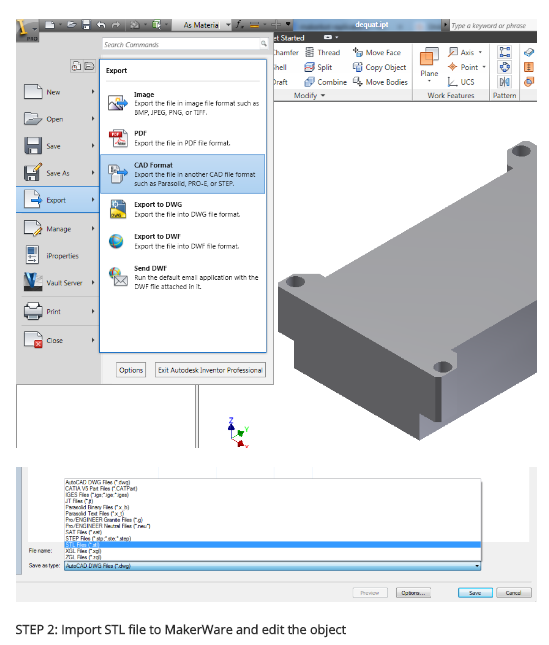
AUTODESK INVENTOR
- Click Application menu > Export > Other Formats. description Find
- dIn the Export Data dialog box, enter a file name.
- Under Files of type, select Lithography (*.stl). Click Save.
- Select one or more solid objects. All objects must be entirely within the positive XYZ octant of the world coordinate system (WCS). That is, their X, Y, and Z coordinates must be greater than zero.
How to Convert 3D Models into STL Files
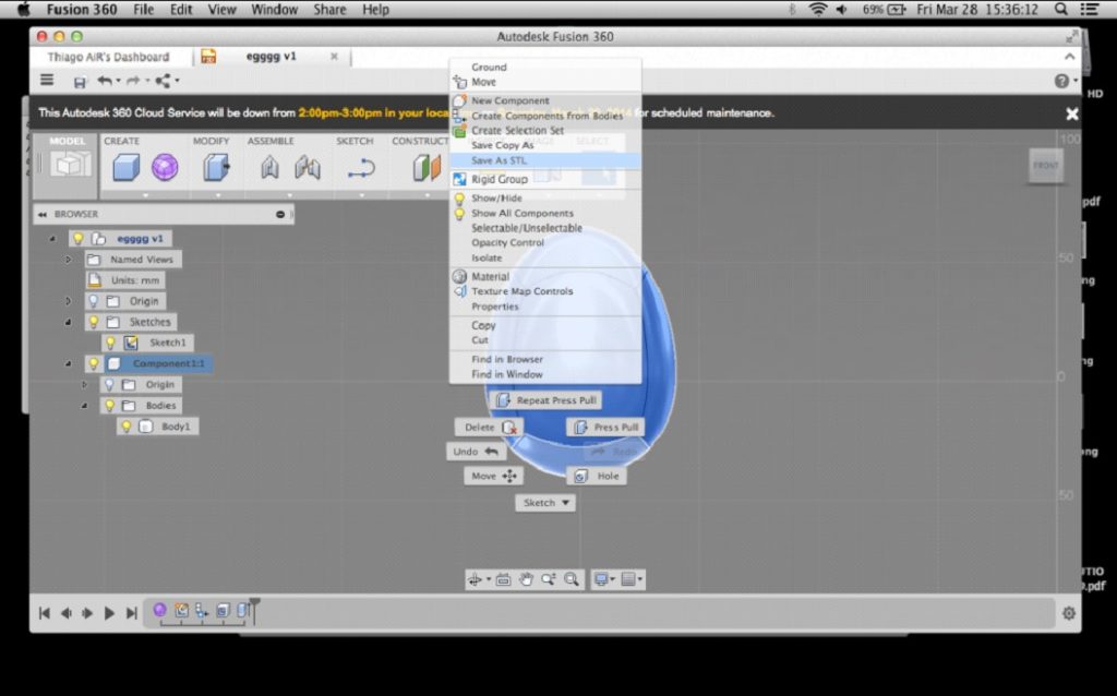
AUTODESK FUSION
How to Convert 3D Models into STL Files
CATIA
- Select STL command (we recommend setting maximum segmentation to 0.015 mm)
-
dSelect the model > Yes > Export
Note: CATIA V5 software is used for converting catpart to stl files, so it converts catpart to stl files, but not from assemblies (CATProduct files) or geometrical representations (car files). Therefore, source files, including those saved in a neutral format (i.e. STEP or IGES), must be saved as CATParts. If the source design was saved as an assembly, it is imported to CATIA as a CATProduct. To create an STL file from it, you must first convert it to a multi-bodied part. The procedure described below is one of several methods for doing this. STL files can be saved - with the special add on module. catia V5 is capable of creating & converting catpart to stl files from parts(catia PARATS files), not from assemblies (catia product files) or geometrical representation(car files). Therefore, source files, include those saved in a neutral format (STEP OR IGES ,for example)must be saved as parts.
Saving CATProduct files as CATPart Files for 3D printing: - File Menu > Open > select your source file (assemblies import as CATProduct)
- Save the imported CATProduct file
- Select File > New > Part > Name the new part
- Select one component from your master CATProduct File and copy it
- Paste the component in a new part window
- Repeat steps and until you have copied all of the components and pasted them as individual parts
- Once you have the assembly completely separate into individual components, select File > New Part
- Copy each of the individual components from the working files and paste them into the new combined model file (the geometries of all of the parts should retain and align correctly in the combined part)
- The new part is now ready to be exported as an STL file
- Select Tools > Generate CATPart from Product
-
Finally, Select File > Salve As > Save as type: STL
Tip: Occasionally some of the components may not align correctly in the combined part because of the way the original assembly was designed. To align parts, select Insert Menu > Constraints Feature. Tip: Curves’ accuracy ratio: The higher the setting, the smoother the surface will be when dealing with complex geometries, especially if surfaces contain sudden small changes with small radii (like the bumps on a golf ball). Before saving the file, it is advisable to review the settings that determine model accuracy and file size. To see these parameters: - Tools > Options
- Under the general category (on the left), select display
- Select File > New > Part > Name the new part
- Review 3D Accuracy settings
How to Convert 3D Models into STL Files
PRO/ENGINEER
- File > Export > Model
- STL
- Set chord height to 0. The field will be replaced by minimum acceptable value
- Set Angle Control to 1
- OK
To save a Pro/Engineer as an STL file:
- Check that the model design is continuous and “watertight.” This step is especially important if the design was imported from a neutral design format. Non-continuous bodies are likely to result in defective models. You cannot always check for continuity by examining the model displayed in shaded view. Therefore, use the following method
- View the model with hidden lines displayed
- From the View menu, select Display Setting > Scheme > PreWildfire. The model surfaces are displayed in magenta. If the design is continuous, the contour lines are white. If there are gaps, the lines are yellow
- Fix the model design, if necessary, before saving it as an STL file
- From the File menu, select Save a Copy. The Save a Copy dialog box appears. From the Type pull-down menu, select STL.
Deviation Control
The Deviation Control settings in the Export STL dialog box affect the accuracy of the model and the size of its file. Chord Height – Also known as “chordal tolerance,” this setting specifies the maximum distance between the surface of the original design and the tessellated surface of the STL triangle (the chord). Therefore, the chord height controls the degree of tessellation of the model surface. The smaller the chord height, the less deviation from the actual part surface (but the bigger the file).
Angle Control
Saving a Pro/E Assembly as an STL File
- Check that the model design is continuous and “watertight.” This step is especially important if the design was imported from a neutral design format. Non-continuous bodies are likely to result in defective models. You cannot always check for continuity by examining the model displayed in shaded view. Therefore, use the following method
- From the File menu, select Save a Copy. The Save a Copy dialog box appears
- From the Type pull-down menu, select STL. The Export STL dialog box appears. In addition to the settings used when exporting a part STL, this dialog box enables you to specify the parts of an assembly to either include or exclude from the resulting STL file. In the dialog box one of the parts of the assembly (the tire) has been excluded, leaving two parts (the hub and the main wheel) to be exported to the STL file. The design resulting from these settings (when you click OK) is shown on the left.
- When you have made all of the required settings, click Apply and OK to create the STL file
How to Convert 3D Models into STL Files
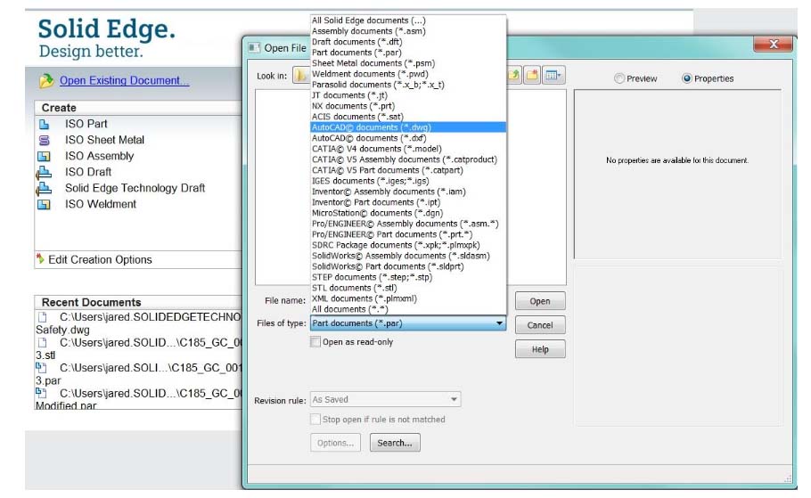
SOLID EDGE
Solid Edge ST6 – ST8
- Application Button > Save As (opens dialog box)
- From the Save As drop down menu, select STL documents (*.stl)
- Select the Options button from the Save As dialog box
-
Adjust Conversion Tolerance and Tolerance Units (millimeters recommended)
* The lower the conversation tolerance, the finer the tessellation -
Adjust the Surface Plane Angle (dependent your desired surface smoothness)
* The lower the surface plane angle, the greater the accuracy (noticeable in small details)
* As a rule, the finer the tessellation and the greater the accuracy, the larger the size of the STL file, and the longer it takes to generate it -
Under Output File as: Check Binary
* Binary STL files are much smaller than STL files saved in ASCII format - Click OK > Save
Note: Solid Edge is capable of creating individual STL files from the components of an assembly, but this functionality is not built into the program. It is achieved through the application programming interface (API), using Visual Basic scripts. This solution does not enable a visual preview of the polygon mesh before saving the STL files.
Solid Edge (Older than ST6)
- Open model and select File > Save As
- Save As Type >STL
- Options > Conversion Tolerance: 0.0254 mm for FDM; 0.015 mm for PolyJet
- Set Surface Plane Angle to 45°
- Select Binary type and OK
- Name and Save STL file
Note: Solid Edge software from Siemens PLM (formerly USG) supports STL output at the core level, enabling you to save both parts and assemblies as STL files. However, when saving an assembly, all of its components are included in a single STL file.